Table of Contents
Table of Contents
- Introduction to Vintage Computer Power Supplies
- Understanding Common Failure Modes
- Essential Tools and Equipment
- Safety Considerations and Precautions
- Diagnostic Procedures and Testing
- Capacitor Replacement Techniques
- Transformer Testing and Repair
- Voltage Regulation Troubleshooting
- Step-by-Step Restoration Process
- Preventive Maintenance Strategies
- Parts Sourcing and Compatibility
- Troubleshooting Flowcharts
- Advanced Repair Techniques
- Quality Control and Testing
- Downloadable Resources
1. Introduction to Vintage Computer Power Supplies
Vintage computer power supply units (PSUs) represent a critical component in maintaining and restoring classic computing systems from the 1970s through the 1990s. These power supplies, ranging from simple linear designs to more complex switching topologies, require specialized knowledge and techniques for proper restoration and repair.
Understanding the evolution of computer power supply technology is essential for any restoration project. Early systems like the Altair 8800 and Apple II used relatively simple linear power supplies, while later machines such as the IBM PC and Commodore Amiga incorporated more sophisticated switching power supplies that offered better efficiency and smaller form factors.
Key Characteristics of Vintage Power Supplies
- Linear regulation technology in early systems
- Switching topology adoption in the 1980s
- Multiple voltage rails (+5V, +12V, -12V, -5V)
- Lower power requirements compared to modern systems
- Proprietary connector systems and form factors
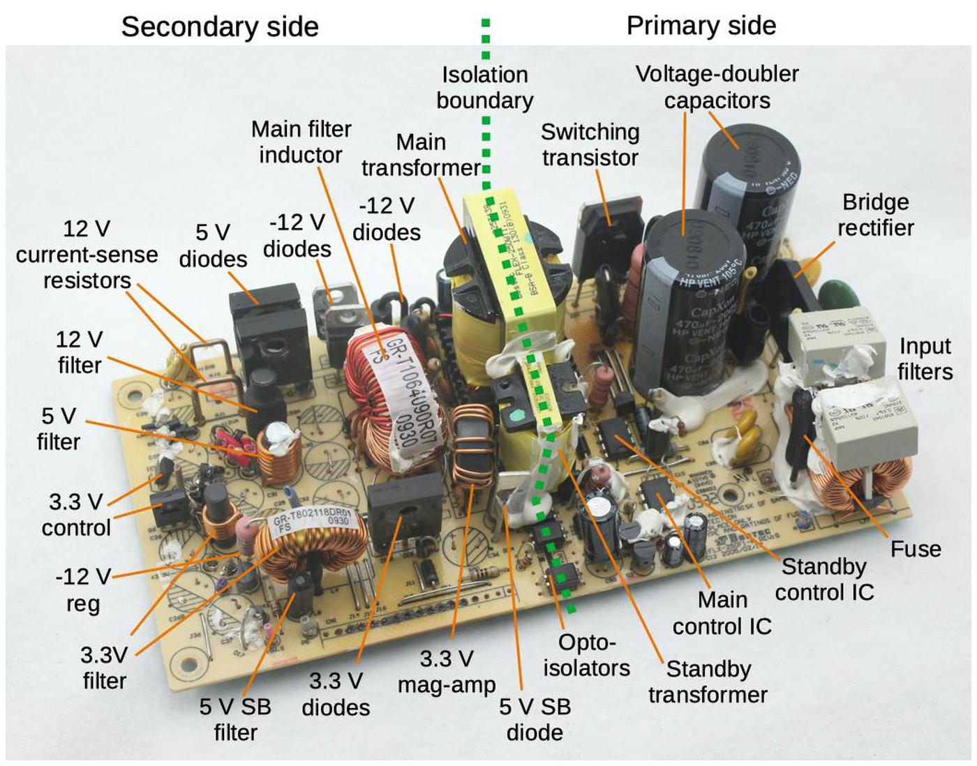
The restoration of vintage computer power supplies requires a deep understanding of both the electrical principles involved and the specific characteristics of different eras of computer design. This comprehensive guide provides the knowledge and techniques necessary to successfully diagnose, repair, and restore these essential components.
2. Understanding Common Failure Modes
Vintage computer power supplies exhibit predictable failure patterns that have developed over decades of operation. Understanding these common failure modes enables efficient diagnosis and targeted repair strategies that can restore these units to reliable operation.
2.1 Electrolytic Capacitor Degradation
The most prevalent failure mode in vintage power supplies involves the degradation of electrolytic capacitors. These components, essential for filtering and energy storage, experience chemical breakdown over time, leading to reduced capacitance, increased equivalent series resistance (ESR), and potential leakage.
Critical Warning: Aged electrolytic capacitors can fail catastrophically, potentially causing damage to other components or creating safety hazards. Always inspect capacitors thoroughly before powering up vintage equipment.
| Failure Type | Symptoms | Typical Age | Risk Level |
|---|---|---|---|
| Capacitance Loss | Increased ripple, voltage instability | 15-25 years | Medium |
| ESR Increase | Poor regulation, heating | 20-30 years | High |
| Electrolyte Leakage | Visible corrosion, component damage | 25-40 years | Critical |
| Physical Bulging | Deformed capacitor case | 30+ years | Critical |
2.2 Switching Transistor Failures
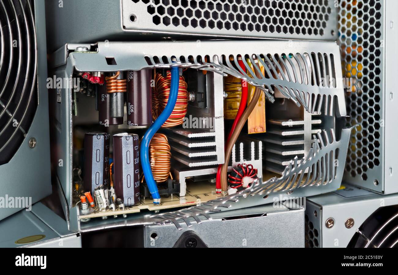
In switching power supplies, the power transistors responsible for the switching action frequently fail due to thermal stress, voltage spikes, or gate drive issues. These failures often manifest as complete power supply shutdown or erratic operation.
2.3 Transformer and Inductor Issues
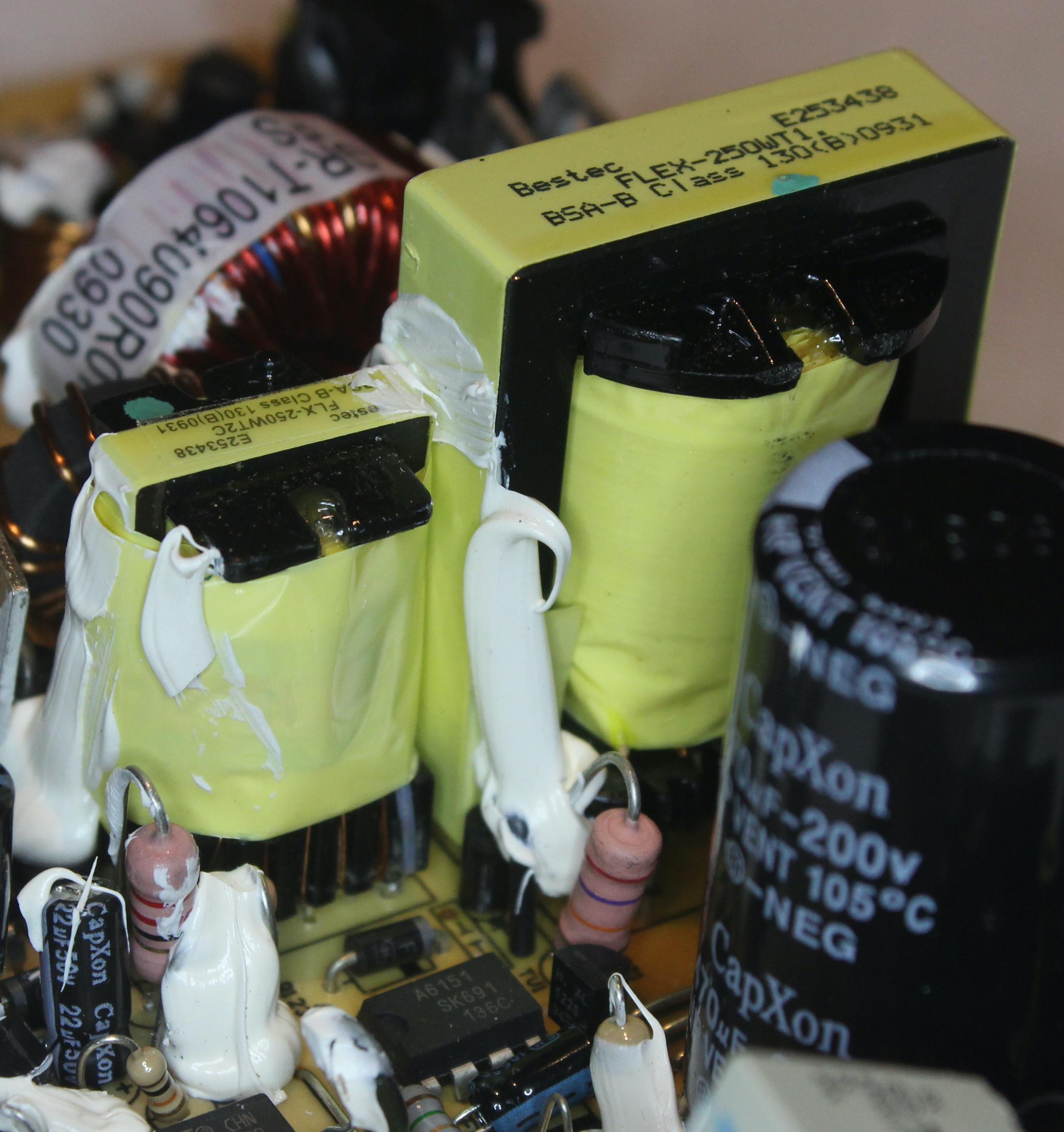
Magnetic components in vintage power supplies can develop various problems including insulation breakdown, core saturation, and winding failures. These issues often result from environmental factors, manufacturing defects, or electrical stress over time.
3. Essential Tools and Equipment
Professional vintage computer power supply restoration requires specialized tools and equipment to ensure safe, effective, and reliable repairs. The following comprehensive tool list represents the minimum requirements for serious restoration work.
3.1 Basic Hand Tools
| Tool | Specification | Purpose | Recommended Brand |
|---|---|---|---|
| Screwdriver Set | Phillips, Flathead, Torx | Case disassembly | Klein Tools |
| Desoldering Station | Temperature controlled | Component removal | Hakko FR-300 |
| Soldering Iron | 40-60W adjustable | Component installation | Weller WES51 |
| Wire Strippers | 16-26 AWG | Wire preparation | Klein 11047 |
3.2 Test Equipment
Accurate diagnosis and verification of repairs requires professional-grade test equipment. While vintage-specific analyzers are ideal, modern digital instruments can provide the necessary measurements with proper technique.
Professional Tip: When selecting test equipment for vintage power supply work, prioritize accuracy and safety features over advanced digital interfaces. Many vintage circuits operate at voltages and frequencies that can challenge modern meter specifications.
| Instrument | Key Specifications | Primary Use | Amazon Link |
|---|---|---|---|
| Digital Multimeter | True RMS, 0.1% accuracy | Voltage, current, resistance | Fluke 87V |
| Oscilloscope | 100MHz, 2-channel minimum | Waveform analysis | Rigol DS1054Z |
| ESR Meter | In-circuit testing | Capacitor evaluation | Peak ESR70 |
| Variable Load | 0-10A, 0-30V | Load testing | Electronic Load |
3.3 Safety Equipment
Vintage power supply restoration involves potentially lethal voltages and requires appropriate safety equipment. Never compromise on safety equipment quality or proper procedures when working with electrical systems.
Safety Warning: Vintage power supplies can retain dangerous voltages even when unplugged. Always use proper safety equipment and follow established safety procedures.
4. Safety Considerations and Precautions
Working with vintage computer power supplies presents unique safety challenges that require careful attention to proper procedures and equipment. The combination of high voltages, aged components, and unfamiliar circuit topologies demands a methodical approach to safety.
4.1 Electrical Safety Protocols
Establishing and maintaining proper electrical safety protocols is fundamental to successful vintage power supply restoration. These protocols must account for the specific characteristics of vintage equipment and the potential hazards associated with aged components.
Critical Safety Notice: Many vintage power supplies operate with lethal voltages exceeding 300V DC. Capacitors can retain dangerous charges for extended periods even after power disconnection. Always follow proper discharge procedures.
- Pre-Work Inspection: Thoroughly examine the power supply for obvious damage, bulging capacitors, or signs of previous repair attempts before beginning work.
- Proper Discharge Procedures: Use appropriate discharge tools to safely dissipate stored energy in capacitors before handling components.
- Isolation Verification: Confirm complete electrical isolation using proper test equipment before beginning hands-on work.
- One-Hand Rule: When taking measurements on live circuits, keep one hand behind your back to prevent creating a current path across your chest.
4.2 Component Handling Precautions
Vintage electronic components require special handling considerations due to their age and potential fragility. Proper component handling techniques prevent damage and ensure successful restoration outcomes.

5. Diagnostic Procedures and Testing
Effective diagnosis of vintage power supply problems requires a systematic approach that combines visual inspection, electrical testing, and functional verification. The diagnostic process must account for the specific characteristics and failure modes common to vintage equipment.
5.1 Visual Inspection Protocol
The diagnostic process begins with a comprehensive visual inspection that can reveal many common problems without the need for electrical testing. This inspection should follow a systematic approach to ensure no potential issues are overlooked.
Visual Inspection Checklist
- Capacitor condition (bulging, leakage, corrosion)
- Resistor discoloration or thermal damage
- Transformer or inductor physical condition
- PCB condition (cracks, corrosion, burn marks)
- Connector integrity and corrosion
- Fuse condition and rating verification
5.2 Electrical Testing Procedures
Following visual inspection, systematic electrical testing provides detailed information about power supply performance and identifies specific component failures. These tests should be performed in a logical sequence to build understanding of the circuit’s condition.
| Test Procedure | Equipment Required | Expected Results | Failure Indicators |
|---|---|---|---|
| Primary Fuse Continuity | Multimeter | < 0.5Ω resistance | Open circuit, infinite resistance |
| Input Rectifier Check | Diode tester | 0.6-0.8V forward drop | Short circuit or no conduction |
| Filter Capacitor ESR | ESR meter | < 1Ω for main filter | High ESR > 5Ω |
| Output Voltage Regulation | Multimeter, variable load | ±5% of nominal | Poor regulation > ±10% |

6. Capacitor Replacement Techniques
Capacitor replacement represents the most common and critical repair procedure in vintage power supply restoration. Proper technique ensures reliable operation and prevents future failures while maintaining the original circuit characteristics.
6.1 Capacitor Selection Criteria
Selecting appropriate replacement capacitors requires understanding the specific requirements of vintage power supply circuits. Modern capacitors offer improved reliability and performance, but compatibility considerations must be carefully evaluated.
Professional Tip: When replacing electrolytic capacitors in vintage power supplies, select components with voltage ratings at least 20% higher than the original specification to account for component tolerances and aging effects.
| Specification | Original vs. Replacement | Recommended Approach | Quality Brands |
|---|---|---|---|
| Capacitance | Match or slightly higher | ±20% maximum increase | Nichicon, Panasonic |
| Voltage Rating | Equal or higher | 120% of original minimum | Rubycon, Elna |
| ESR Rating | Lower preferred | Use low-ESR types | Panasonic FM series |
| Temperature Rating | 105°C minimum | Match application requirements | Nichicon UPW series |
6.2 Removal and Installation Techniques
Proper capacitor removal and installation techniques are essential for successful restoration work. These procedures must minimize thermal stress on the PCB while ensuring reliable electrical connections.

- Preparation: Clean the work area and ensure proper ventilation for soldering operations.
- Component Marking: Document the original capacitor orientation and specifications before removal.
- Desoldering: Use appropriate temperature settings and techniques to minimize PCB damage.
- Hole Cleaning: Ensure mounting holes are clean and properly sized for new components.
- Installation: Install new capacitors with proper orientation and secure mounting.
- Soldering: Create reliable solder joints without excessive heat or duration.
7. Transformer Testing and Repair
Transformer testing and repair in vintage power supplies requires specialized knowledge and techniques. While many transformer problems can be detected through electrical testing, some issues require mechanical inspection and repair procedures.
7.1 Transformer Testing Procedures
Comprehensive transformer testing involves multiple measurement techniques to evaluate both electrical and mechanical condition. These tests must account for the specific characteristics of vintage transformer construction and materials.
| Test Type | Measurement | Acceptable Range | Failure Indicators |
|---|---|---|---|
| Primary Resistance | DC resistance | Datasheet ±10% | Open or short circuit |
| Secondary Resistance | DC resistance | Datasheet ±10% | Open or short circuit |
| Insulation Resistance | Primary to secondary | > 10MΩ | Low resistance < 1MΩ |
| Turns Ratio | Voltage ratio | Calculated ratio ±5% | Significant deviation |
8. Voltage Regulation Troubleshooting
Voltage regulation problems in vintage power supplies often stem from component aging, thermal stress, or feedback system failures. Systematic troubleshooting approaches can isolate these issues and guide appropriate repair strategies.
8.1 Linear Regulator Troubleshooting
Linear voltage regulators in vintage power supplies commonly experience failures related to pass transistor degradation, reference voltage drift, or thermal protection activation. Understanding these failure modes enables targeted diagnostic approaches.
Common Linear Regulator Problems
- Pass transistor thermal failure
- Reference voltage drift
- Feedback network component aging
- Thermal protection false triggering
- Output capacitor ESR increase
8.2 Switching Regulator Troubleshooting
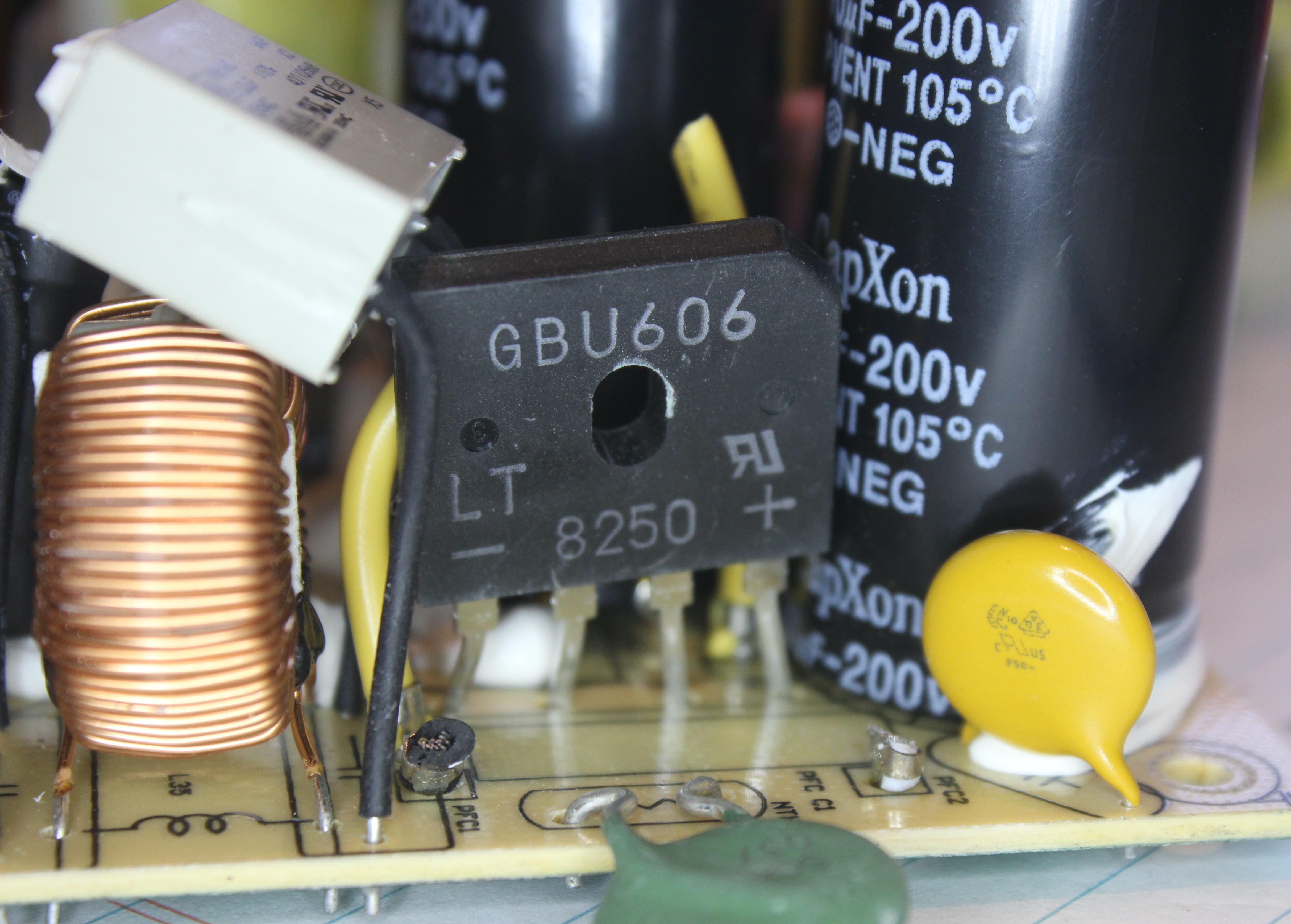
Switching regulators present more complex troubleshooting challenges due to their dynamic operation and multiple feedback loops. These systems require specialized diagnostic techniques and understanding of switching power supply principles.
9. Step-by-Step Restoration Process
The restoration process for vintage computer power supplies follows a systematic approach that ensures thorough evaluation, proper repair, and reliable operation. This process must be adapted to the specific characteristics of each power supply type and condition.
9.1 Initial Assessment and Documentation
Proper documentation of the original power supply condition and specifications provides the foundation for successful restoration. This documentation serves as a reference throughout the restoration process and helps verify final results.
- Photographic Documentation: Take detailed photographs of the power supply before disassembly, including label information, component placement, and any visible damage.
- Schematic Research: Locate original schematics or create reverse-engineered documentation for reference during restoration.
- Component Inventory: Document all major components, their specifications, and condition assessment.
- Performance Baseline: If possible, establish baseline performance measurements before beginning restoration work.
9.2 Disassembly and Component Evaluation
Systematic disassembly allows for thorough component evaluation and identification of all required repairs. This process must be carefully documented to ensure proper reassembly.
Restoration Tip: Create a detailed disassembly log with photographs at each step. This documentation proves invaluable during reassembly, especially with complex vintage power supplies that may lack service documentation.
9.3 Component Replacement and Repair
The component replacement phase requires careful attention to compatibility, quality, and proper installation techniques. Priority should be given to components that are known to degrade over time or show signs of failure.

10. Preventive Maintenance Strategies
Preventive maintenance for vintage computer power supplies extends their operational life and reduces the likelihood of unexpected failures. These strategies must account for the specific aging characteristics of vintage components and environmental factors.
10.1 Scheduled Maintenance Intervals
Establishing appropriate maintenance intervals for vintage power supplies requires understanding component life expectancy and operating conditions. Regular maintenance prevents minor issues from developing into major failures.
| Maintenance Task | Frequency | Procedure | Expected Benefit |
|---|---|---|---|
| Visual Inspection | 6 months | Check for component swelling, corrosion | Early failure detection |
| Capacitor ESR Testing | 2 years | In-circuit ESR measurement | Predict capacitor failures |
| Thermal Inspection | 1 year | IR thermography or thermal monitoring | Identify thermal stress |
| Contact Cleaning | 1 year | Clean connectors and switches | Maintain electrical integrity |
11. Parts Sourcing and Compatibility
Sourcing appropriate replacement parts for vintage power supplies requires understanding component specifications, availability, and compatibility issues. Modern components often offer improved performance, but compatibility considerations must be carefully evaluated.
11.1 Component Sourcing Strategies
Successful parts sourcing for vintage power supply restoration requires multiple approaches and supplier relationships. Understanding component specifications and acceptable substitutions is essential for cost-effective restoration.
Recommended Parts Sources
- New Components:Mouser Electronics, Digi-Key, Amazon Electronics
- Obsolete Components: Rochester Electronics, Brokers
- Salvage Sources: eBay, Electronics recyclers
- Specialty Suppliers: Console5, Amiga specialists
11.2 Cross-Reference and Substitution Guidelines
Component substitution in vintage power supplies requires careful analysis of electrical specifications, physical compatibility, and circuit requirements. Proper substitution techniques can improve reliability while maintaining original performance characteristics.
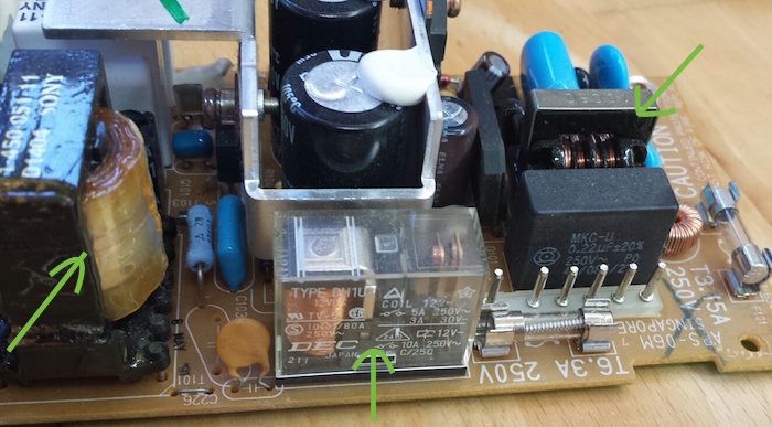
12. Troubleshooting Flowcharts
Systematic troubleshooting flowcharts provide structured approaches to diagnosing vintage power supply problems. These flowcharts must account for the specific failure modes and characteristics of vintage equipment.

12.1 No Output Voltage Troubleshooting
Complete power supply failure requires systematic diagnosis starting with basic safety checks and progressing through circuit analysis. This troubleshooting approach isolates failures efficiently while minimizing risk.
- Safety Verification: Confirm power disconnection and capacitor discharge
- Fuse Inspection: Check primary and secondary fuses for continuity
- Input Rectifier Testing: Verify bridge rectifier operation
- Filter Capacitor Evaluation: Test main filter capacitors for function
- Switching Circuit Analysis: Examine switching transistors and drive circuits
- Transformer Verification: Test transformer windings and turns ratio
13. Advanced Repair Techniques
Advanced repair techniques for vintage power supplies involve complex procedures that require specialized equipment and expertise. These techniques address difficult problems that cannot be resolved through standard component replacement.
13.1 Circuit Board Repair and Restoration
PCB damage in vintage power supplies often requires specialized repair techniques including trace repair, via reconstruction, and laminate restoration. These procedures must maintain electrical integrity while preserving mechanical stability.
Advanced Technique Warning: PCB repair procedures require specialized materials and techniques. Improper repairs can compromise electrical safety and reliability. Consider professional repair services for complex PCB damage.
13.2 Custom Component Fabrication
When original components are unavailable, custom fabrication techniques can provide suitable replacements. These techniques require understanding of component specifications and manufacturing processes.
14. Quality Control and Testing
Comprehensive quality control and testing procedures ensure that restored vintage power supplies meet safety and performance requirements. These procedures must verify all aspects of power supply operation under various load conditions.
14.1 Performance Verification Testing
Performance verification testing confirms that restored power supplies meet original specifications and provide reliable operation. These tests must simulate actual operating conditions and stress levels.
| Test Parameter | Test Condition | Acceptance Criteria | Test Duration |
|---|---|---|---|
| Output Voltage Accuracy | Full load, nominal input | ±3% of nominal | 30 minutes |
| Load Regulation | No load to full load | ±5% variation | 15 minutes |
| Ripple and Noise | Full load, worst case | < 100mV peak-to-peak | 10 minutes |
| Thermal Stability | Continuous operation | No thermal runaway | 2 hours |
14.2 Safety Verification Procedures
Safety verification ensures that restored power supplies do not present electrical hazards to users or connected equipment. These procedures must confirm proper grounding, insulation, and protection circuit operation.
Safety Testing Tip: Always perform safety verification testing before returning restored power supplies to service. Document all test results for future reference and warranty purposes.
15. Downloadable Resources
The following downloadable resources provide additional technical information, reference materials, and practical tools for vintage computer power supply restoration projects.
Available Downloads
- Vintage Power Supply Schematics Collection – Comprehensive collection of original schematics for popular vintage computer power supplies
- Component Cross-Reference Database – Detailed cross-reference information for obsolete components and modern equivalents
- Troubleshooting Checklist – Printable checklists for systematic diagnosis and repair procedures
- Safety Procedures Manual – Complete safety procedures and emergency response guidelines
- Parts Sourcing Guide – Comprehensive supplier information and ordering guidelines
- Test Equipment Setup Guides – Detailed setup procedures for various test equipment configurations
Additional Resources
For the most current technical information and community support, visit the following resources:
- Vintage Computer Power Supply Forum – Active community discussion
- Technical Application Notes – Manufacturer-specific guidance
- Video Tutorials – Visual demonstrations of repair techniques
- Supplier Catalogs – Current availability and pricing information
Conclusion
Successful vintage computer power supply restoration requires a combination of technical knowledge, proper equipment, and systematic procedures. By following the guidelines and techniques presented in this comprehensive guide, restoration enthusiasts can achieve professional results while maintaining the safety and reliability essential for vintage computer operation.
The investment in proper tools, quality components, and thorough procedures pays dividends in the form of reliable operation and extended service life for these important pieces of computing history. Whether restoring a simple linear power supply from the 1970s or a complex switching unit from the 1980s, the fundamental principles and techniques outlined in this guide provide the foundation for successful restoration projects.
Remember that vintage computer power supply restoration is both an art and a science, requiring patience, attention to detail, and respect for the electrical hazards involved. With proper preparation and technique, these classic power supplies can be restored to provide many more years of reliable service, preserving our computing heritage for future generations.
Final Recommendations
- Always prioritize safety over speed or convenience
- Document all work for future reference and troubleshooting
- Use quality components and proper techniques for lasting results
- Test thoroughly before returning equipment to service
- Continue learning and staying current with restoration techniques
This guide represents current best practices in vintage computer power supply restoration. Technology and techniques continue to evolve, and restorers should stay informed about new developments and safety requirements in this specialized field.
