
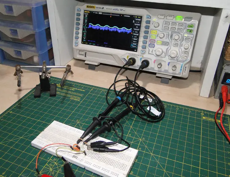
How do you Connect an Oscilloscope?
Connect the scope probe’s ground clip to the ground plain or connection of the circuit, and the probe tip to the signal output of the circuit. When these connections are made the oscilloscopes screen will instantly display a line which is known as the signals waveform.
What is an Oscilloscope used for?
The primary use of an oscilloscope is to create a real time graph of an electrical signal as it chages over time. Nearly all oscilloscopes display a two-dimensional graph that shows time on the x-axis and voltage on the y-axis.
Oscilloscopes can be very useful when trying to test or diagnose a faulty electrics circuit.
What are the different types of oscilloscope?
Several types of oscilloscopes are available, both analog and digital, for a range of prices. Since digital oscilloscopes can miss some transient signals, analog oscilloscopes are still prized for transient troubleshooting applications. However, high-end digital phosphor oscilloscopes can provide similar capabilities.
Analog Oscilloscopes
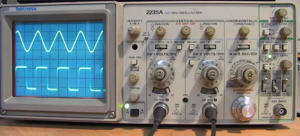
An analog oscilloscope displays the signal picked up by a probe and traces it on the screen. Storage capabilities allow the waveform to display for extended periods of time rather than decay immediately.
Digital Oscilloscopes
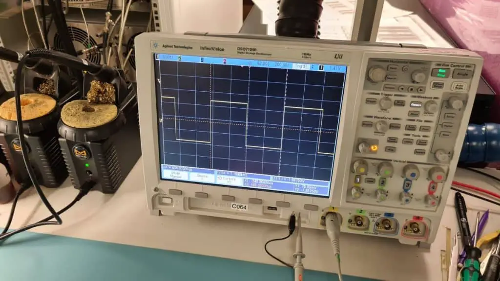
Digital oscilloscopes are available in many types. Two key factors determine the performance of a digital oscilloscope: sampling rate and bandwidth. An oscilloscope’s sampling rate limits its ability to capture transient, one-time events. The bandwidth of an oscilloscope limits the frequency of repetitive signals that can be displayed. You can get one here: https://amzn.to/2YNIuUk
Handheld Oscilloscopes
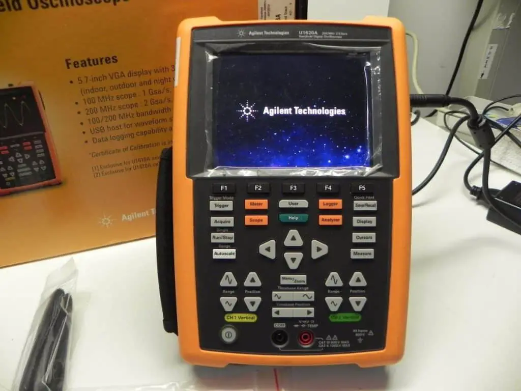
Small handheld oscilloscopes are available for field and test applications where bulkier oscilloscopes are unwieldy or power outlets are unavailable. These typically contain two inputs and have limited sampling rates and bandwidth. You can get one here: Amazon.com
How to use an Oscilloscope to measure Voltage
To measure voltage on an oscilloscope follow these directions:
Make sure your scope is plugged in and switched on. Then press the default setting button on the front.
Make sure there is a scope probe plugged into the channel one BNC socket on the front of the scope. Ensure that the probe has grounding clip plugged into it.
Look for a grounding point such as a pad or trace on the circuit and attach the ground clip to it.
Touch the probe tip to the trace, pad or component leg on the circuit board that contains the signal that you want to measure.
The oscilloscope will now measure the signal’s voltage and display it in real time as it varies. If nothing is displayed on the screen, press the Auto Scale button on the front panel of the scope to display your waveform at a scale that is fully visible on the screen.
If you need to adjust the signal displayed any more just use the vertical and horizontal controls for the scope channel that you are using. These controls will allow you zoom in and out and also adjust the position of the wave form right, left, up, and down. To display a more accurate wave form, ensure the wave forms width is spanning most of the width of the screen.
The straight forward way to measure the voltage of the waveform on the display is to count the number of screen divisions from top to bottom of the signal and multiply the number by the value of the the vertical scale measured in volts per division. Notice that the divisions will be labeled in volts on the Y-axis so this is a lot easier to calculate the voltage of the waveform with the help of these labels.
Most modern oscilloscopes now have the ability to automatically measure the voltage and other measurements without the need to counting division marks manually.
How to Calculate Frequency from an Oscilloscope
To measure frequency of a signal you need to count the number of horizontal divisions from one of the peaks of the waveform to the next instance of the repeated peak. Then multiply the number of horizontal divisions by the time per division. This will calculate the signal’s period. Once you have calculated the perion of the wavefore you can now calculate the signal’s frequency with the following equation.
frequency = 1/period
What is a Division on an Oscilloscope?
A division on an oscilloscope is the distance between the two lines of a square on the oscilloscope’s screen. A setting of . 5 for example means, that the height of a single square equals a voltage of 0.5 V. An amplitude of 1 V would have a size of two divisions.
How can an Oscilloscope be used to Test Circuits?
The basic procedure for testing an electronic circuit with an oscilloscope is to attach the ground connector of the scope’s test lead to a ground point in the circuit, and then touch the tip of the probe to the point in the circuit that you want to test.
Can I Measure Current with an Oscilloscope?
Normally most oscilloscopes cannot measure current as standard. They can only directly measure Voltage. Only with the use of a current clamp can a scope measure current but these probes can be very expensive.
Can we use the oscilloscope to measure DC voltages?
Yes ocilloscopes can measure a DC votage. Any DC voltage signal will be displayed on the screen as a straight line.
What is Oscilloscope Trigger?
The trigger function of an oscilloscope is very important to display a clear signal on the screen, it synchronizes the horizontal sweep of the oscilloscope to create a still image and stops it from jumping or moving about on the screen so accurate measurements can be made. The trigger control will help you to stabilize any repetitive waveforms and also allow you to capture a single-shot waveform.
What is Oscilloscope Gain?
It is possible to measure the gain or amplification of a circuit by using both channel one and channel two simltaniously. You use channel one to monitor the input signal and channel two to measure the output signal. A setting on the scope will allow you to dislpay the calculated difference between the input signal and the output signal. This is the gain or amplification of the circuit.
How many Signals can an Oscilloscope Display at once?
Most modern oscilloscopes can display at least two or more signals at a time and therefore would have a BNC connector on the front panel for each signal or trace. These connectors are also called Y-Inputs.
What is the Time Base on an Oscilloscope?
An oscilloscope basically plots voltage against increasing time. The main elements of the oscilloscope is a X-Y display, a voltage amplifier and a timebase.The voltage amplifier is tied to the X or vetical axis of the display. The time base is connected to the horizontal axis of the display.
The increasing time is represented by a increasing voltage that looks like a ramp. The ramp repeats in a sawtooth so that the plot repeats on the scope.In the sophisticated scopes the time base is triggerable to that an external cyclical event can synhcronize the sweep so that the fleeting X-Y plot becomes stable to view.
Digital scopes have the same functions but use a memory based X-Y plot that is much easier to single-shot for one time events.So the timebase in very simple terms sets the timespan of the horizontal axis and sometimes its offset.