Multimeters are useful instruments that can convey a lot about a signal with voltage, current, strength and continuity.. Some more modern multimeters are available and can also calculate inductivity and power, making them very useful for analogue circuits.
Multimeters can also be used in digital settings, but for a variety of reasons they are often unacceptable. First, the multimeters are equipped to monitor DC or AC sources, so the multimeter is able to register odd voltages if the numerical signal is switched on. Second, multimeters are huge and voluminous, but it can be impossible to use more than three on a circuit. Third, the multimeters have a standard input (floor) to connect and can make this a challenging job when using more than two.
A logic probe is a very basic circuit designed to calculate digital processes, unlike a multimeter. Typically only 3 output LEDs that indicates the following states are fitted with logic samples.
- 1 – (Digital High)
- 0 – (Digital Low)
- Z – (High impedance)
- P – (Signal is pulsing / switching)
However, analogue readings cannot be measured by logic samples, so the voltage of the signal levels cannot be calculated for calculating signals. Despite this weakness, logic samples with other samples are quickly built, assembled and used. The logic sample we will construct will be made up of four different logic sample circuits combined to a single circuit with four LED output and four logic sample inputs.
What is a logic probe?
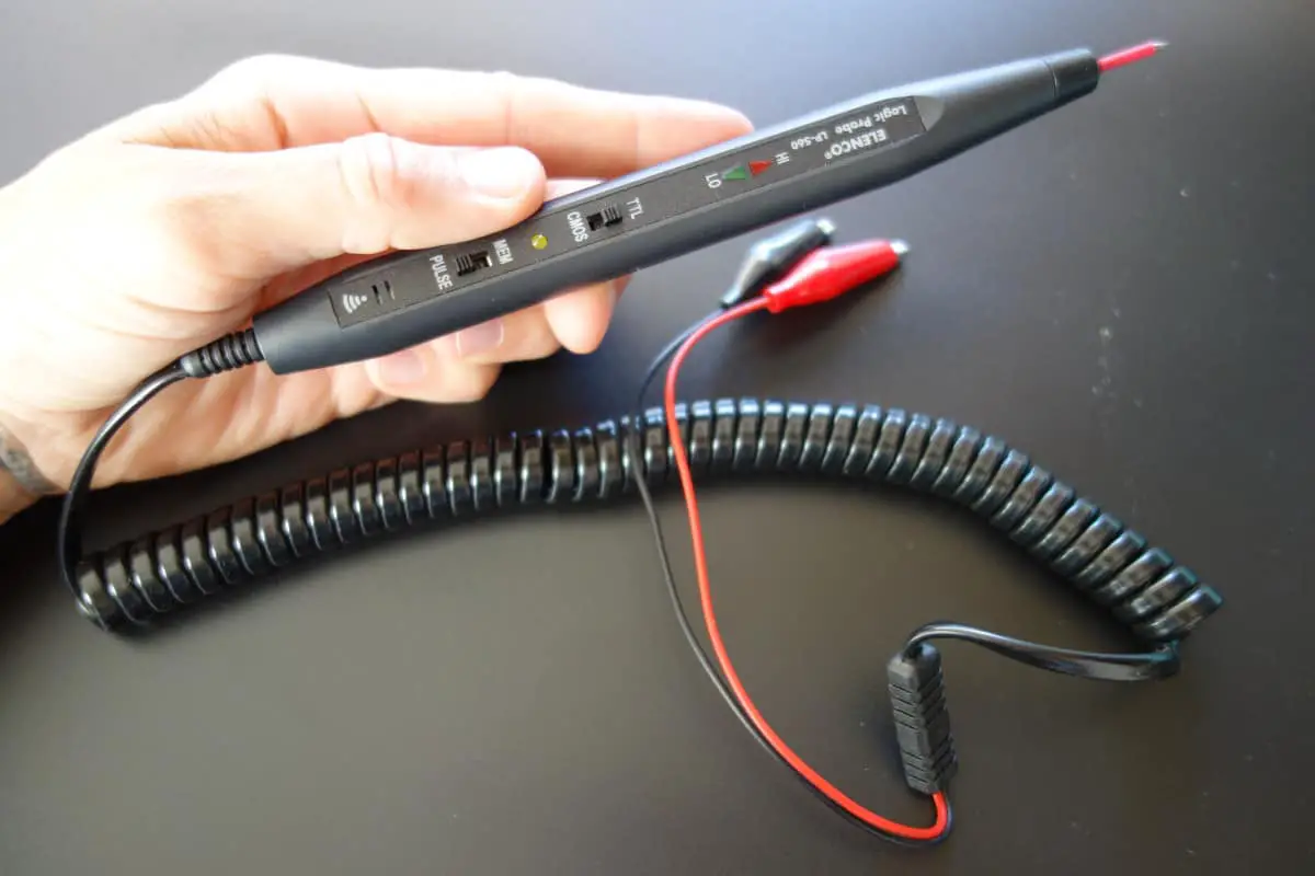
The logic probe or digital tester is normally a low cost handheld probe contained within a pen-like tube with indicator lights to show the state of the line being probed.
Typically logic probes are used to test digital circuits like those using TTL or CMOS logic. They often have three indicator lights on the body to indicate the state of the line. As such logic probes are very basic forms of digital testers, only able to test the state of a single line, but they can be useful in many applications.
The logic probe is normally powered by the circuit under test – there are normally leads with crocodile / alligator clips that can be attached to the ground and supply of the circuit under test.
Logic probe measurements
A logic probe is restricted in the number of measurements it can make when compared to other test instruments, but it can nevertheless be used for a variety of digital measurements:
- Logic high state: The logic probe / digital logic tester is able to detect lines that are at the digital or logic high state. The logic probe will indicate this typically with an LED which is often coloured red.
- Logic low: The logic probe also is able to indicate a logic or digital low. A common indication is with the use of a green coloured LED.
- Digital pulses: The logic probe may incorporate some form of pulse detection circuitry. When the line is active and being pulsed a third colour, possibly amber will be indicated. The logic probe may well incorporate circuitry to detect very short pulses and in this way indicate when the line is active. Sometimes the length of the pulses may be indicated by the brightness of the LED.
- Line tri-stated: Some logic probes may also be able to detect when a line has been put into a tristate option. This is when the output device has its output turned off and no real logical state is defined. Many logic probes are able to indicate this state and they may do this by having all indicators turned off.
Logic probes vary from one manufacturer the next and therefore it is necessary to check exactly what measurements can be made and how the results are indicated.
Advantages and disadvantages of a logic probe
As with any item of test equipment, there are advantages and disadvantages to the use of a logic probe tester than need to be considered before buying or using one.
Logic probe advantages –
- Low cost: A logic probe does not contain much circuitry, and the display is very rudimentary. Therefore the cost of manufacture is very low – they can typically be bought for less than the cost of a very basic multimeter. Logic analyzers and mixed signal oscilloscopes cost very many times more than logic probes.
- Ease of use : To use a logic probe typically requires the connection of power leads and then connecting the probe to the required point on the circuit.
Logic probe disadvantages –
- Very rough measurement: The nature of the logic probe means that only an indication of the presence of a logic signal can be detected. It is not replacement for a test instrument such as an oscilloscope.
- Poor display: A logic probe only uses a few LEDs to indicate the nature of the logic signal. As a result, little information can be displayed about the nature of the logic signal that is detected.
What is a Multimeter?
A digital multimeter is a test tool used to measure two or more electrical values—principally voltage (volts), current (amps) and resistance (ohms). It is a standard diagnostic tool for technicians in the electrical/electronic industries.
Digital multimeters long ago replaced needle-based analog meters due to their ability to measure with greater accuracy, reliability and increased impedance. Fluke introduced its first digital multimeter in 1977.
Digital multimeters combine the testing capabilities of single-task meters—the voltmeter (for measuring volts), ammeter (amps) and ohmmeter (ohms). Often, they include several additional specialized features or advanced options. Technicians with specific needs, therefore, can seek out a model targeted to meet their needs.
The face of a digital multimeter typically includes four components:
- Display: Where measurement readouts can be viewed.
- Buttons: For selecting various functions; the options vary by model.
- Dial (or rotary switch): For selecting primary measurement values (volts, amps, ohms).
- Input jacks: Where test leads are inserted.
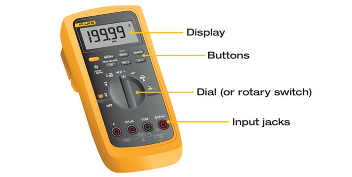
Test leads are flexible, insulated wires (red for positive, black for negative) that plug into the DMM. They serve as the conductor from the item being tested to the multimeter. The probe tips on each lead are used for testing circuits.
The terms counts and digits are used to describe a digital multimeter’s resolution—how fine a measurement a meter can make. By knowing a multimeter’s resolution, a technician can determine if it is possible to see a small change in a measured signal.
Example: If a multimeter offers a resolution of 1 mV on the 4 V range, it is possible to see a change of 1 mV (1/1000th of a volt) while reading 1V.
Digital multimeters are typically grouped by their number of counts (up to 20,000) they display.
Broadly speaking, multimeters fall into one of a handful of categories:
- General purpose (aka Testers)
- Standard
- Advanced
- Compact
- Wireless
Need help choosing which multimeter is right for you? Use the Digital Multimeter Tool Selector.
Safety
Each application with a digital multimeter presents potential safety hazards that must be considered when taking electrical measurements. Before using any electrical test equipment, people should always first refer to the user’s manual for proper operating procedures, safety precautions, and limits.