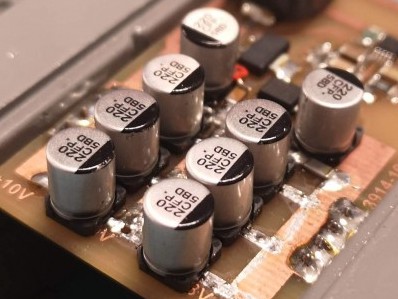
Surface-mount (SMD) capacitors look intimidating the first time you see them, but they are very manageable with a fine-tipped iron, good flux and a little patience. If you restore retro hardware, you will meet them sooner or later: the Amiga 600, Amiga 1200 and CD32 use SMD electrolytic capacitors that now need replacing.
The video below shows the process. This guide explains each step, the polarity markings to watch for, and how to tell a good joint from a bad one.
Types of SMD capacitor
- Ceramic chip capacitors: small rectangular blocks, usually tan or grey, with no markings. They are not polarised, so they can go either way round.
- Aluminium electrolytic capacitors: small cans on a square plastic base. They are polarised.
- Tantalum capacitors: small rectangular moulded parts, often yellow, orange or black. They are polarised.
Polarity: the most important check
Getting polarity wrong on an electrolytic or tantalum capacitor can make it fail, sometimes violently. The markings are confusingly opposite:
| Type | Marking | Meaning |
|---|---|---|
| SMD aluminium electrolytic | Dark band or shaded segment on the top | Marks the negative (−) side |
| Tantalum | Stripe or bar at one end | Marks the positive (+) side |
| Ceramic | None | Not polarised |
The circuit board’s silkscreen usually shows polarity too, often with a shaded half or a plus sign. Before removing an old part, take a photo and note the orientation. If you are recapping, see our guide to removing surface-mount capacitors first.
Tools you need
- A temperature-controlled iron with a fine conical or small chisel tip. See our guide to the best soldering station for SMD work.
- A flux pen or tacky flux. See the best flux for SMD soldering.
- Fine solder, around 0.5mm.
- Fine-tipped tweezers.
- Magnification: a magnifying lamp or a USB microscope makes a big difference.
- Isopropyl alcohol and a brush for cleaning off flux.
Step 1: Prepare the pads
Clean the pads with isopropyl alcohol. If you have just removed an old capacitor, remove the old solder with solder wick so the pads are flat. On boards like the Amiga 1200, where old capacitors have leaked, make sure all electrolyte residue is cleaned off, as it is corrosive.
Step 2: Tin one pad
Add a small amount of flux to the pads, then melt a small blob of solder onto one pad only. Choose the pad that is easiest to reach with your dominant hand.
Step 3: Tack the capacitor in place
Hold the capacitor with tweezers in the correct orientation. Melt the solder on the tinned pad and slide the capacitor’s lead into it, keeping the part flat on the board. Remove the iron and hold the part still for a second while the solder sets.
Check the part is straight and properly aligned with the second pad. If not, reheat the first joint and adjust.
Step 4: Solder the second side
Add a little flux, then solder the second lead: touch the iron to the pad and the lead together, and feed in a small amount of solder. It should flow smoothly onto both surfaces.
Step 5: Reflow the first side
Go back to the first joint and reheat it with a little flux, so it flows properly. The tacking joint is often not perfect.
Step 6: Clean and inspect
Clean off flux residue with isopropyl alcohol and a brush. Under magnification, a good joint has a smooth, concave fillet that runs from the pad up the side of the lead. Look out for:
- Too little solder: the lead is not fully wetted.
- Too much solder: a large ball that may hide a poor joint.
- Bridges: solder connecting the joint to a nearby pad or track.
- Tombstoning: one end of a small chip capacitor lifted off its pad.
Using hot air
A hot air station is useful for removing old parts and for very small chip capacitors. Use flux, a gentle airflow so small parts are not blown away, and protect nearby plastic parts with Kapton tape. For a beginner, the iron method above is often easier to control for capacitor replacement. You can also use solder paste.
Through-hole substitutes
On some retro boards, people replace SMD electrolytic capacitors with modern solid polymer or ceramic types, or fit through-hole parts with bent legs. Check the value, voltage and size, and follow a known recap guide for your machine. See our guide to replacing capacitors in vintage electronics.
FAQ
Which side of an SMD electrolytic capacitor is negative?
The side with the dark band or shaded segment on the top of the can is negative.
Which side of a tantalum capacitor is positive?
On a tantalum capacitor, the stripe or bar marks the positive end. This is the opposite of most electrolytic capacitors.
Can I solder SMD capacitors with a normal soldering iron?
Yes. A temperature-controlled iron with a fine tip, flux and fine solder is enough for most SMD capacitors. Hot air helps but is not essential.
Do ceramic SMD capacitors have polarity?
No. Ceramic chip capacitors are not polarised and can be fitted either way round.